Skip table of contents

[ENG] Planning diagram of electricity, water and equipment

Screen Name

Planning diagram of electricity, water and equipment

Login → Energy Management → Planning Structure

Summary

The Planning Structure is designed for the operations department to manage all electrical and water equipment, allowing for the planning and measurement of consumption metrics for each device.

1. Create planning locations and create devices.

image-20241006-080315.png

image-20241006-080356.png

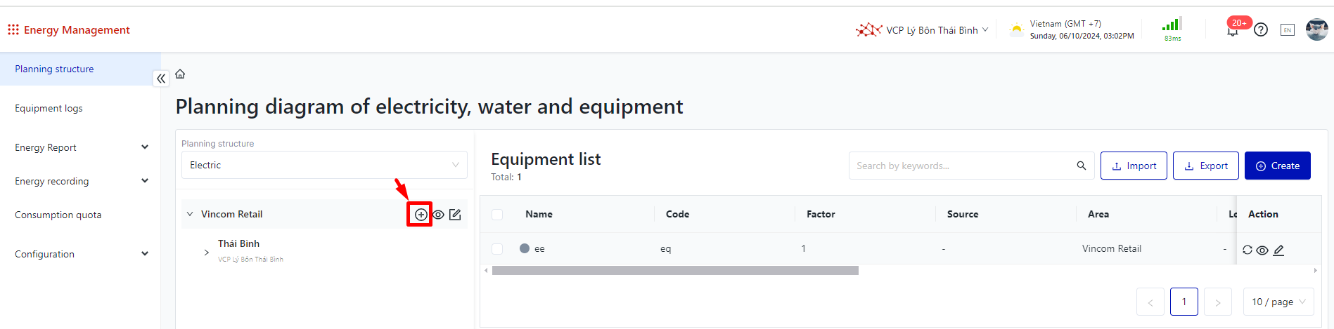
Step 1: Create Planning Structure

  • Code: Required (maximum 64 characters)

  • Name: Required (maximum 512 characters)

  • Parent Location: Displays the parent location information

  • Labeel: Optional, currently available types are: Base, Transformer Station, Level 1, Level 2, Level 3

  • Link to the unit tree of recording consumption data (Corporation, Region, facility): Optional

Step 2: Create Equipment
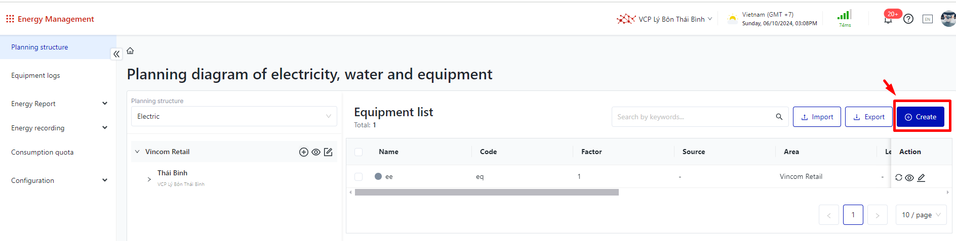
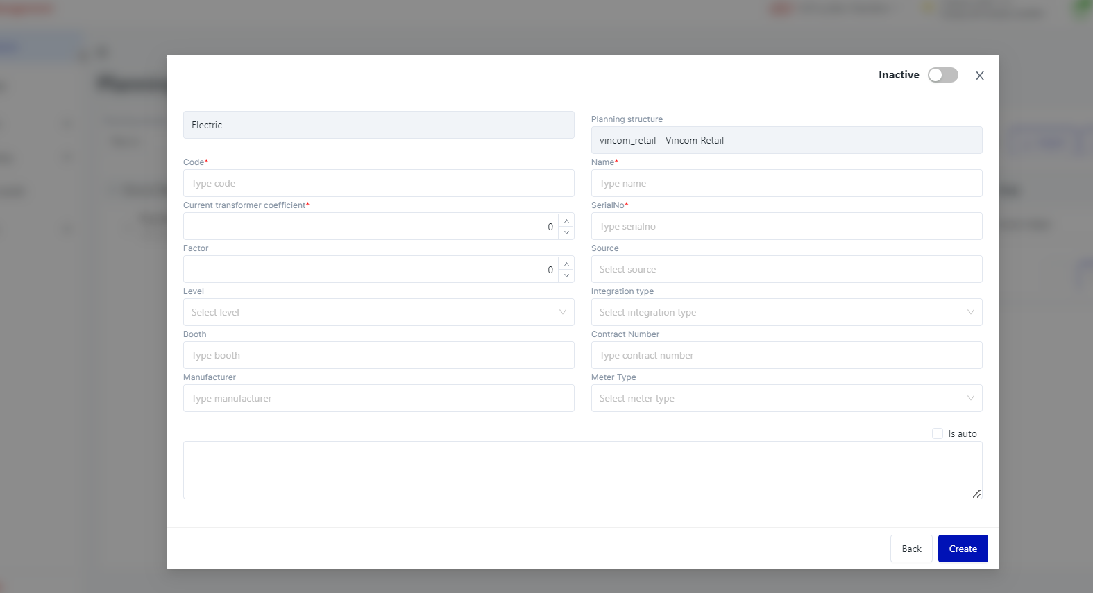
image-20241006-080855.png
image-20241006-080937.png

  • System: Displays electricity/water

  • Planning structure: Displays according to the established structure

  • Code: Required (maximum 64 characters)

  • Name: Required (maximum 512 characters)

  • Current transformer coefficient: Required

  • Serial Number: Required

  • Factor: Optional

  • Source: Optional

  • Level: Optional, currently available types are: Base, Transformer Station, Level 1, Level 2, Level 3

  • Integration Type: Emic (automatically recorded checkbox) / Other (manual recording)

  • Booth: Optional

  • Contract Number: Optional

  • Manufacturer: Optional

  • Meter Type: Optional

  • Description: Optional (maximum 512 characters)

  • Status: Active / Inactive

2. WEB Operations

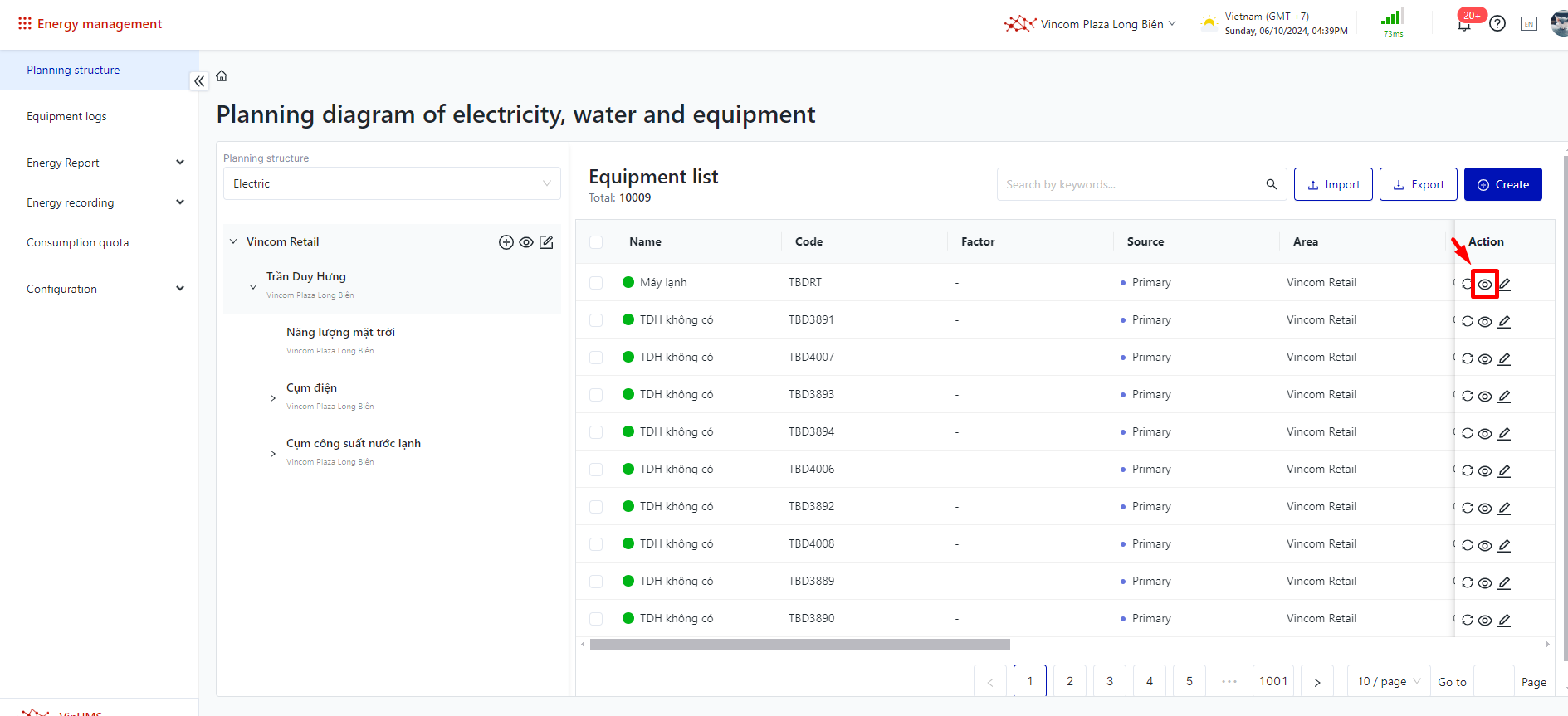
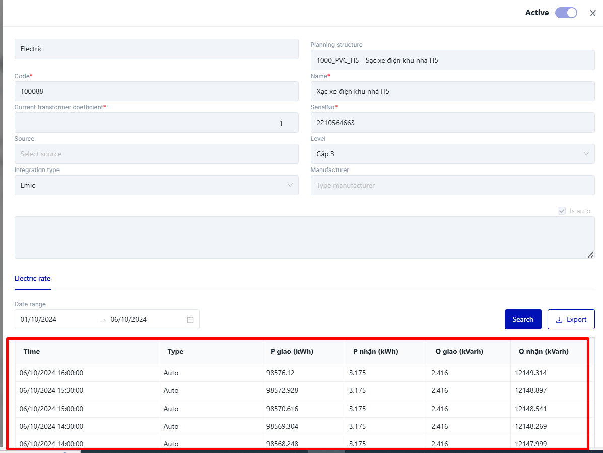
2.1. Viewing Information Automatically Recorded from Emic (Currently Applicable Only to Electrical Systems):

  • Click on "View Details," where users can view and manipulate the following parameters:

    • View information on P sent, P received, Q sent, Q received, type of recording, and filter by time period.

    • Download the displayed information.

image-20241006-094014.png

image-20241006-094625.png

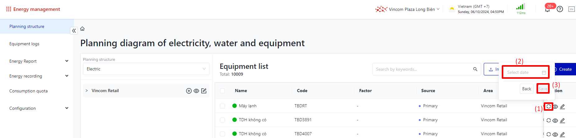
2.2. Synchronizing Automatically Recorded Information from Emic:

  • (1) : Click the "Synchronize" button image-20241006-095744.png

  • (2) : Filter by a specific time frame.

  • Then click save.

image-20241006-095211.png

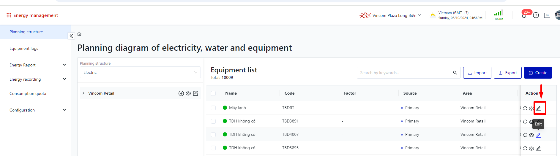
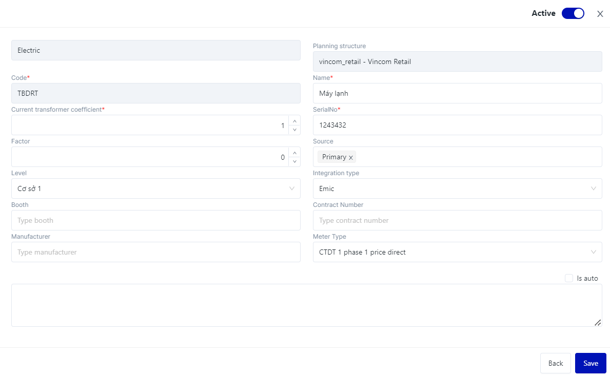
2.3. Edit Equipment :

  • click on “Edit” image-20241006-095720.png

image-20241006-095703.png

image-20241006-095815.png

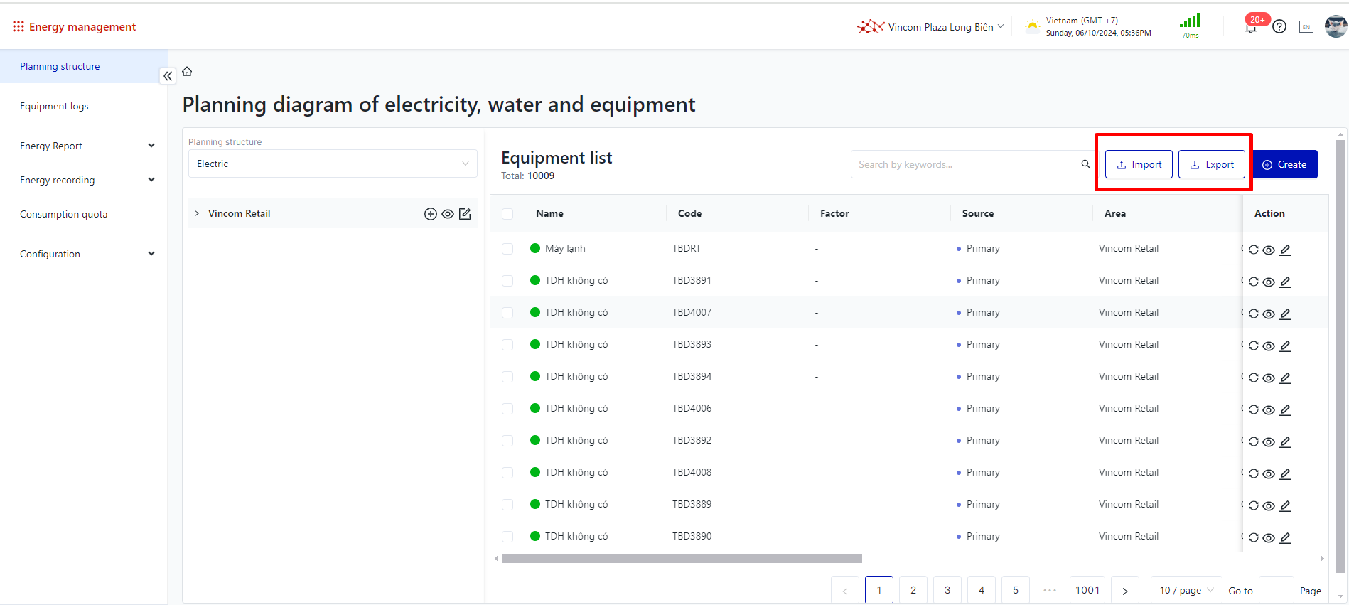
2.4. Delete equipment :

Equipment can only be deleted if no recorded values have been generated (this applies to both manual and automatic recordings).

image-20241006-100101.png

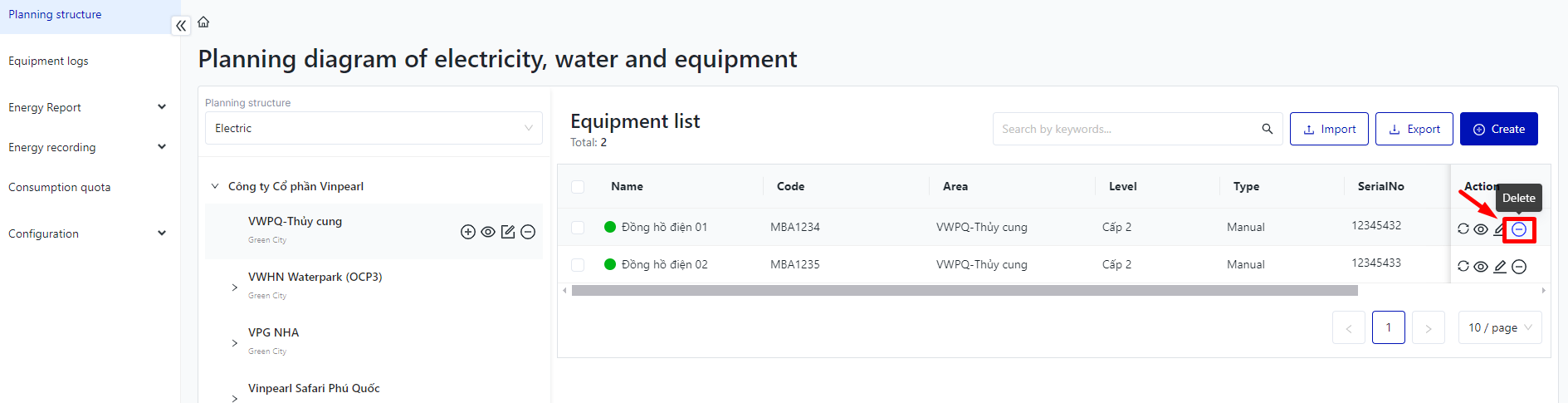
If recorded data exists, the system will prevent deletion and display the following message. Click "No" to close the pop-up.

image-20240730-044722.png

2.5. Import/ Export equipment

  • Import: Users download template file, fill in the required information correctly, and then upload it. (Note: When downloading the equipment list, do not modify any column information.)

  • Export: click to export quipment list

image-20241006-103626.png

image-20241006-103924.png

3. Printing Barcode/QR code on each equipment

Step 1: Checkbox the box to select all euipment that need to be printed.

image-20241006-104333.png

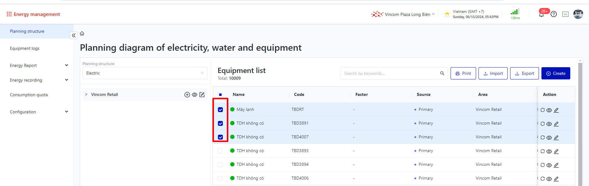
Step 2: Click on “Print”, then choose the desired format for printing the barcode/QR code.

image-20241006-104424.png

image-20241006-104549.png

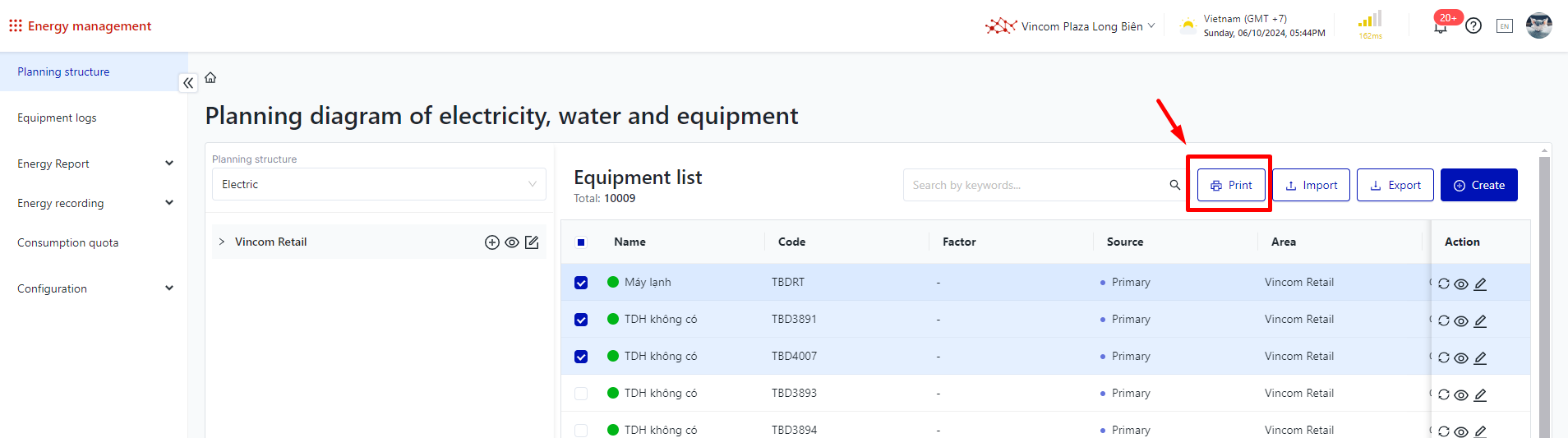
Step 3: Connect the printer and print all corresponding equipment codes.
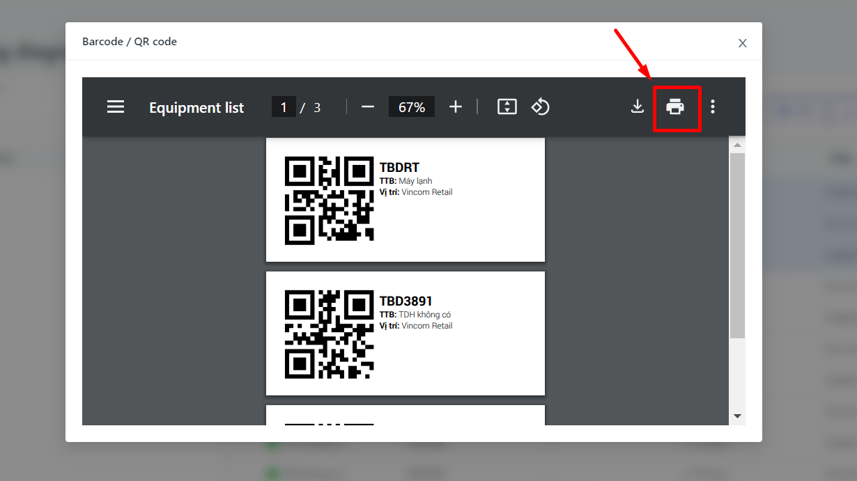
image-20241006-104702.png

JavaScript errors detected

Please note, these errors can depend on your browser setup.

If this problem persists, please contact our support.